3 Phase Transformer Primary and Secondary Current Calculation
In many cases youll want to calculate the primary voltage which is the voltage the transformer receives from a power source. Both these phase sequences are determined by how the 3-phase transformer supply lines L1 L2 L3 are connected and labeled.
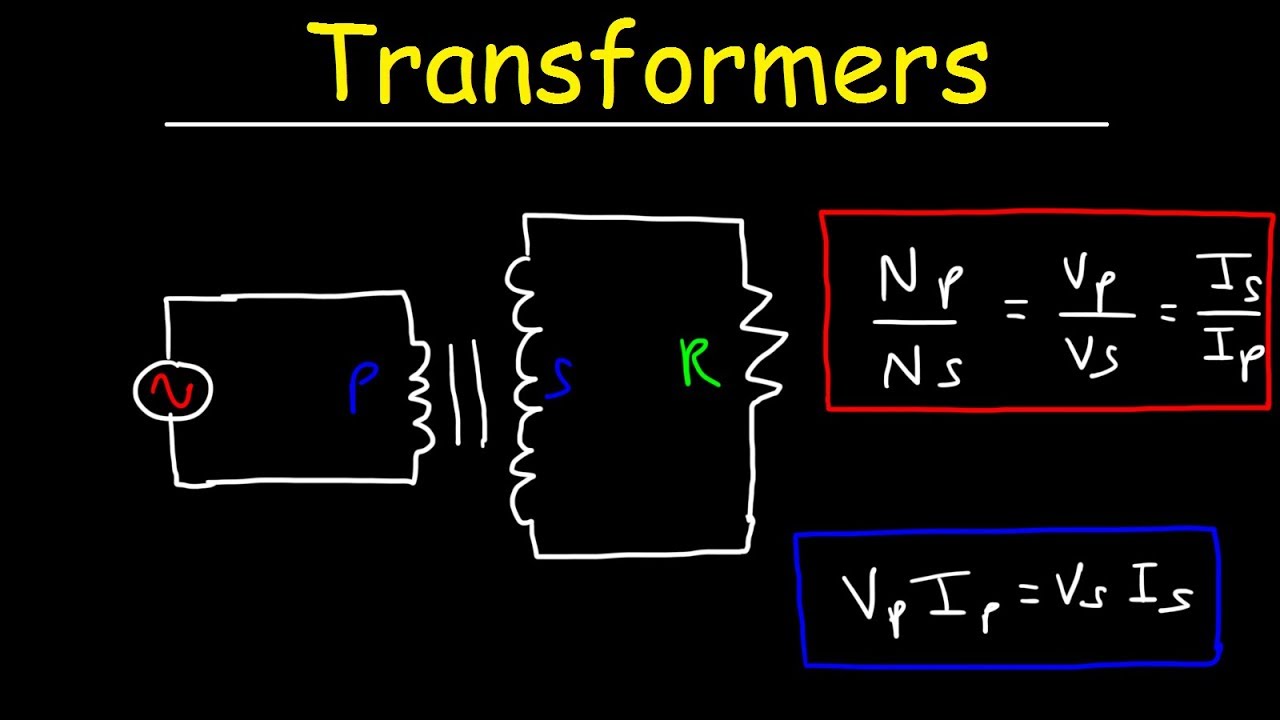
Transformers Physics Problems Voltage Current Power Calculations Electromagnetic Induction Youtube
It is used for referring to the circular cross-sectional area of the wire or conductor.
. You can determine that primary voltage by using the ratios of current and voltage from the transformers primary and secondary coils. This configuration connects two or more transformers fed from at least two feeders in parallel to energize the secondary bus. Can be used to calculate the forces between two conductors in the event of a 3 phase.
Basic principles The transformer may be considered as a simple two-wheel gearbox for electrical voltage and current. For a 480 Volt rated primary if 96 volts causes. I keep getting 22 cause I add the 80 load into my calculation joeldjiogo August.
To prevent reverse power flow through the transformers special network protectors with sensitive reverse power relays are used. Special application metering CTs are a special category in which it is desired that the CT should accurately measure the current from 1 to 120 of the rated current. Figure 4 illustrates the 3-2-1 sequence relative to the 1-2-3 sequence.
Transformer impedance is determined as follows. Determine the secondary current rating. If the secondary rated current is 5A this meter shall measure current from 50 mA to 6A accurately.
The maximum flux in the core. There are only two valid phase sequences. It is caused by the generated alternating flux in the transformer core.
The maximum value of the magnetic flux density is 11T when 2200 volts 50Hz is applied to the transformer primary winding. You calculate available fault current either by getting the figure from the utility at the service point or you can get a worst-case value from the specs of the transformer. Type of Supply Voltage.
Voltage is increased on the primary until full load current flows in the secondary. This 9-0-9 transformer converts 220 volts of AC supply to 9 volts of AC. Spot Networks are used for customers with the highest reliability requirements.
The Current Transformer CT. The 1-2-3 sequence and the 3-2-1 sequence. Transformer full load current I A in amps for single-phase transformer is equal to 1000 times of transformer rating S kVA in kVA kilo Volt-Amp divided by the primary V P-V or secondary voltage V S-V in volts of the transformer.
9-0-9 is a center tapped step down transformer. The transformer secondary is short circuited. The no-load test is performed to determine the no-load losses or core losses as well as the turns ratio no-load currents magnetization components and core loss components of the transformer.
Is a type of instrument transformer that is designed to produce an alternating current in its secondary winding which is proportional to the current being measured in its primaryCurrent transformers reduce high voltage currents to a much lower value and provide a convenient way of safely monitoring the actual electrical current flowing in an AC. In this comparison current is equivalent to shaft speed and voltage to shaft torque. Transformer Phase Shift.
Core Loss or Iron loss. This type of CT is used for revenue meters and in energy meters. You need to know the KVA the impedance Z the secondary voltage and 1-phase vs 3-phase to get the worst-case value of secondary-side available fault current.
Delta-Wye transformers have a 30-degree phase shift which is discussed below. I m lags applied voltage by 90 0. 1 Calculate Short Circuit Current at Substation.
The phase sequence can be changed by simply. Spot networks allow multiple. What size secondary conductor can be used for a 45kVA continuously loaded 3-phase 480V-120208V transformer.
Fault Current At Transformer Secondary IscL-NI L-NTotal Impedance 2. If the transformer is rated in MVA means the formula will be. 9-0-9 Step down Transformer.
There are four different ways in which single phase transformers can be connected to form three phase banks. Available Fault Current Calculation Isc Calculation. Due to hysteresis the magnetization current is not sinusoidal.
I m in a transformer is always constant irrespective of load. A single phase transformer has 480 turns on the primary winding and 90 turns on the secondary winding. In a center tap transformer a wire is connected exactly at the midpoint of the secondary winding of the transformer and kept at zero volts by connecting it to neutral current.
Each phase of a transformer is composed of two separate coil windings wound on a common core. Maybe you know. Sometimes core loss is known as Magnetizing current Loss or Constant Loss.
I A S kVA 1000 V V. In a gearbox mechanical power speed multiplied by torque is. Circular Mils and Voltage Drop Calculation.
A circular mil is really a unit of area. Remember that every transformer has a primary and secondary side. U n Phase to phase voltage.
Wye-Wye and Delta-Delta transformers do not cause any phase shift from primary to secondary. In general the full load current is equal to. The primary winding is analogous to the input shaft The secondary winding is analogous to the output shaft.
Fault Current At Main Panel. E1 is the primary voltage and I1 the primary current E2 the secondary voltage and I2 the secondary current N1 the primary turns and N2 the secondary turns. The voltage drop using mils is given by L Wire length ft P Phase constant 2 meant for single-phase 1732 meant for three-phase.
This applied voltage divided by the rated primary voltage times 100 is the impedance of the transformer. It depends on the core construction and magnetic properties of the core materials like lamination winding thickness lamination resistance component density. Secondary Current Transformer VA Secondary Voltage 1732 I.
![]()
Three Phase Transformer Connections And Basics

Question Video Finding The Number Of Turns On The Primary Coil Of A Transformer Nagwa

How To Calculate Three Phase Transformer Full Load Secondary Current Youtube
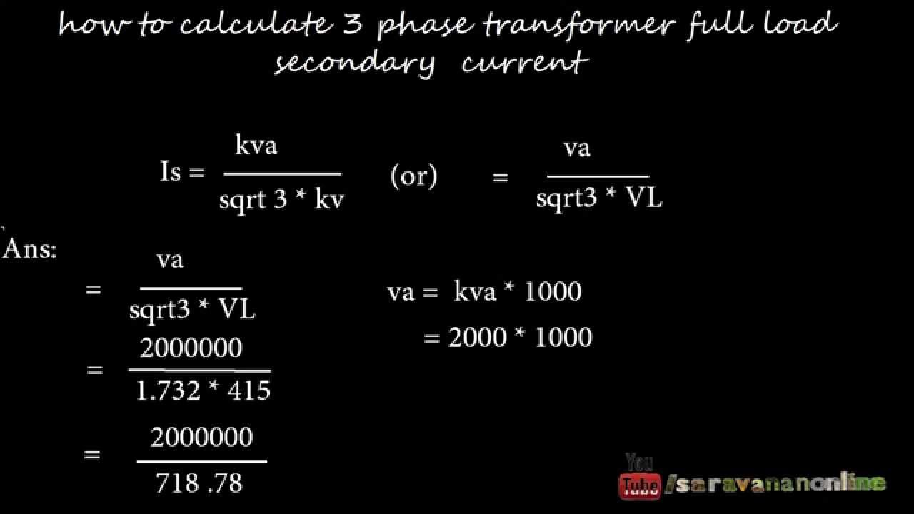
How To Calculate Three Phase Transformer Full Load Secondary Current Youtube


Comments
Post a Comment